This product is not available for new orders. We recommend ordering: CR1000X.
| Services Available | |
|---|---|
| Repair | Yes |
| Calibration | Yes |
| Free Support | No |
Resumen
El CR1000 se ha convertido casi en el estándar industrial de muchas aplicaciones de adquisición de datos y en redes de estaciones de medida. Su alta fiabilidad y bajo consumo hacen que sea muy usado en campo, a menudo en condiciones duras de trabajo y en aplicaciones como meteorología, hidrología, geotecnia, monitorización de estructuras. También es utilizado en red junto con sistemas de control industrial o como equipo de test y ensayos.
El datalogger ofrece una extensa funcionalidad en medida y control, es compatible con una amplia gama de sistemas de comunicaciones, periféricos de expansión y software.
Leer másVentajas y características
- Las aplicaciones ideales incluyen incendios forestales, sistemas mesonet, perfil viento, estación meteorológica, calidad del aire, ETo/agricultura, humedad suelo, nivel agua, acuacultura, aviso aludes, time-domain reflectometry, ensayos automoción, SCADA, y calidad del agua
- Admite comunicaciones serie RS232 con sensores inteligentes y dispositivos compatibles, a través de los puertos COM del datalogger (puertos de control a pares)
- Recoge, almacena datos y controla periféricos, siendo el cerebro del sistema
- Opciones de alimentación y comunicaciones flexibles que lo hacen ideal para aplicaciones remotas.
- La memoria de 4MB se puede ampliar con memoria externa.
- Soporta protocolos PakBus, Modbus, SDI-12 y DNP3
- Compatible con periféricos de ampliación de canales, permitiendo expandir el sistema de adquisición
- Programable con LoggerNet, PC400, o Short Cut
- Opciones varias en comunicaciones: TCP/IP, email, FTP, web server.
- Entradas protegidas por tubos de descarga de gas (GDT)
- Reloj salvaguardado por pila interna, lo cual permite tener en hora el datalogger aunque no haya alimentación externa
- Programación y control en el lugar mediante el teclado/display opcional CR1000KD
- Contiene un chip ASIC que expande la capacidad de contaje de pulsos, puertos de control y comunicaciones serie
Imágenes


Ficheros CAD:
Descripción detallada
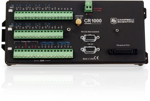
El CR1000 está formado por un módulo de control y medida, y un panel de conexiones. Este datalogger se alimenta externamente y admite teclado/display externo. Su bajo consumo hace que funcione por largos períodos de tiempo aun utilizando una batería recargable con placa solar — sin necesidad de disponer de 220Vac. Cuando la alimentación está por debajo de 9.6 V, se detiene, reduciendo la posibilidad de realizar medidas incorrectas.
El modulo de control y medida se encarga de realizar las medidas de los sensores, gestionar las telecomunicaciones, integrar los datos, controlar dispositivos externos, y almacenar datos y programas en su memoria interna no-volátil. La electrónica interna queda protegida de la RF por su propia carcasa metálica de acero inoxidable.
El reloj interno también está salvaguardado por una pila interna de litio, al igual que los datos almacenados y programas.
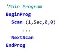
El sistema operativo incluye instrucciones para programar el datalogger: de medida, de procesado de datos y de almacenamiento (output). El lenguaje de programación, denominado CRBasic, usa una sintaxis similar al BASIC. Incluye instrucciones de medida de puentes, voltajes, termopares y pulsos/frecuencia. Las instrucciones de procesado incluyen operaciones algebraicas y estadísticas. Las instrucciones de almacenamiento (salida) procesan los datos a intervalos de tiempo programables y para control de dispositivos externos.
El CR1000WP, fabricado en aluminio anodizado y pintado en negro, se corresponde al panel de conexiones. Incluye tomas de 12Vdc, toma 12Vdc conmutable, tierras analógicas, tubos de descarga de gas para protección transitorios, canales analógicos de entrada, contadores, etc.
El módulo de control (cartucho metálico) y el panel de conexiones CR1000WP, fácilmente se pueden desconectar el uno del otro.
Preguntas frecuentes
Número de FAQs relacionadas con CR1000: 169
Expandir todoDesplegar todo
-
CR1000 dimensions with CFM100 or NL115 attached:
9.9 x 4.0 x 2.8 in.
25.2 x 10.2 x 7.1 cm -
Calibration of the CR1000 is recommended every three years.
-
Yes. The CR1000 is fully programmable to output alarms. The CR1000 can initiate telecommunications such as sending an e-mail or text message, providing audible voice-synthesized information, or calling a pager. The CR1000 can also activate physical alarms, such as sirens and strobes. In this type of installation, a relay device, such as the A6REL-12, is typically used to send a control signal to the alarm device.
-
The potential transformer and the current transformer provide differential outputs that have galvanic isolation from the voltage and current in the circuit they are measuring. However, there is no need to run the outputs of these transformers into differential inputs of the data logger and unnecessarily consume additional data logger channels. We conducted extensive testing for noise immunity, for inaccuracies from ground loops, and more before concluding that single-ended measurements in the ACPower() instruction have the same performance as differential measurements would provide. Please note that as a result of the galvanic isolation of the potential transformer and current transformer, the data logger ground is NOT connected to the ground of the circuit they are measuring.
Said differently, you can connect differential outputs of a sensor to single-ended inputs of the data logger. However, doing so creates the possibility of poor common-mode noise rejection in the data logger and the possibility of introducing inaccuracies from ground loops between the sensor and the data logger. Note that in this application, the transformer isolation of the potential transformer and the current transformer eliminates these concerns.
Simply connect one of the potential transformer secondary wires and one of the current transformer secondary wires to the data logger ground. Which wire in either case makes a difference, as the phase information allows the measurement of power flowing in either direction. If you measure negative real power when it should be positive, then reverse the secondary wires of the potential transformer where they connect to the data logger. Alternatively, you can reverse the secondary wires on the current transformer, but don't reverse both pairs of wires.
-
When idle, the CR1000, CR6, and CR1000X consume less than 1 mA @ 12Vdc. Similar to the CR6, the CR1000X has a much faster processor that requires more power when up and running. As such, there will be higher current draws during active measurements, serial communications, or when plugged into a PC via USB or Ethernet.
It may be helpful to think of the CR6 and CR1000X as being built on the same "platform."
-
A voltage outside of ±5 V present on one of the analog channels can cause self-calibration to fail. Disconnect all sensors, cycle power, and check if the error remains. If self-calibration fails with no sensors attached, consult an application engineer about sending the datalogger to Campbell Scientific for repair.
-
The data structure that is used to store data in the data logger CPU memory cannot be downloaded directly. If the memory of a data logger is expanded using a CompactFlash card, the native TOB3 file can be downloaded using the Connect | File Control | Retrieve… menu.
-
Yes. Create a multidrop network with an MD485 between the CR5000, the CR1000, and the digital modem. See the “Digital Cellular Modem to MD485 Network” appendix item in the MD485 instruction manual.
-
With the CR1000, CR800, CR850, and CR3000, connection between RS-232 ports is possible. The connection requires a null modem serial cable to cross the transmit and receive lines.
-
Yes. Each COM port has individual settings and buffers.
Compatibilidad
Nota: lo siguiente muestra información de compatibilidad notable. No es una lista de todos los productos compatibles.
Medida y Control
| Producto | Compatible | Nota |
|---|---|---|
| SDM-SIO2R |
Software
| Producto | Compatible | Nota |
|---|---|---|
| LoggerNet | Version 3.0 or higher | |
| PC200 (retired) | ||
| PC400 | Version 1.2 or higher | |
| RTDAQ | Version 1.0 or higher | |
| Short Cut |
Miscelaneo
| Producto | Compatible | Nota |
|---|---|---|
| VISUALWEATHER | Version 2.0 or higher |
Información de compatibilidad adicional
Sensores
El CR1000 dispone de diversos tipos de canales de entrada, siendo compatible con casi todos los sensores, incluyendo termopares, sensores SDI-12, o señales 4 a 20mA (con CURS100). Su especial chip ASIC expande las posibilidades de los puertos de control I/O en canales contadores adicionales, comunicaciones serie RS232 y SDI-12.
Periféricos de medida y control
El CR1000 es compatible con todos nuestros módulos SDM, CDM (con SC-CPI), multiplexores, interface de cuerda vibrante, TIMs y relés.
Comunicaciones
El CR1000 puede comunicarse con un PC por conexión directa RS232, interface EtherNet (NL201, NL116, NL121), Wi-Fi NL240, modems multidrop (RS485), modems telefónicos (línea terrestre u línea móvil), radio y satélite (Argos, GOES, Meteosat, Iridium).
Los datos pueden visualizarse in-situ también mediante los teclado/display CR1000K, CD100, CD295, móvil/tableta con iOs o Android (y software LoggerLink), o PDA (con software PConnect o PConnectCE).
Los dispositivos compatibles para almacenamiento de datos externos son el CFM100, NL116, y SC115.
Armarios intemperie
El CR1000 con una fuente de alimentación se ensamblan habitualmente dentro de uno de nuestros armarios.
Alimentación eléctrica
Cualquier fuente de 12Vdc puede alimentar el datalogger CR1000. Habitualmente se usan nuestras fuentes BPALK, PS100 y PS200. La BPALK incluye ocho pilas alcalinas no-recargables que proporciona 7.5Ahr a 20°C.
Tanto la PS150 como la PS200 suministran 12Vdc 7Ahr y regulador de carga. La fuente de carga puede ser tanto una placa solar como un transformador a 220Vac. Estas dos fuentes difieren en el regulador de carga. La PS150 tiene un regulador de carga estándar, mientras que la PS200 lleva un regulador de carga inteligente basado en micro-controlador. El regulador de la PS200 es de voltaje constante de dos pasos con compensación de temperatura que optimiza la carga de la batería e incrementa su vida útil.
También tenemos disponibles las baterías de 12Vdc modelos BP12 y BP24, que proporcionan 12Ah y 24Ah respectivamente. Estas baterías deben conectarse a un regulador (como nuestros CH150 o CH200) y a su vez a una placa solar o transformador a 220Vac.
Software
El CR1000 se programa con el lenguaje CRBasic, el cual permite integración de datos y cálculos. El software compatible es el siguiente:
- Short Cut
- PC200W
- PC400 (version 1.4 o superior)
- LoggerNet (version 3.3 o superior)
- Konect Data Service from Campbell Scientific
- RTDAQ
- PConnect (version 3.3 o superior)
- PConnectCE (version 2.2 o superior)
- VisualWeather (version 2 o superior)
Especificaciones
| -NOTE- | Additional specifications are listed in the CR1000 Specifications Sheet. |
| Operating Temperature Range |
|
| Analog Inputs | 16 single-ended or 8 differential (individually configured) |
| Pulse Counters | 2 |
| Voltage Excitation Terminals | 3 (VX1 to VX3) |
| Communications Ports |
|
| Switched 12 Volt | 1 terminal |
| Digital I/O |
|
| Input Limits | ±5 Vdc |
| Analog Voltage Accuracy | ±(0.06% of reading + offset) at 0° to 40°C |
| ADC | 13-bit |
| Power Requirements | 9.6 to 16 Vdc |
| Real-Time Clock Accuracy | ±3 min. per year (Correction via GPS optional.) |
| Internet Protocols | FTP, HTTP, XML, POP3, SMTP, Telnet, NTCIP, NTP |
| Communication Protocols | PakBus, Modbus, DNP3, SDI-12, SDM |
| Warranty | 3 years |
| Battery-backed SRAM for CPU Usage & Final Storage | 4 MB |
| Idle Current Drain, Average | < 1mA (@ 12 Vdc) |
| Active Current Drain, Average |
|
| Dimensions |
|
| Weight | 1.0 kg (2.1 lb) |
Documentos
Folletos producto
Documentos técnicos
- Data Streaming
- Benefits of Input Reversal and Excitation Reversal for Voltage Measurements
- Preventing and Attacking Measurement Noise Problems
- Voltage Accuracy, Self-Calibration, and Ratiometric Measurements
- DNP3 with Campbell Scientific Dataloggers
- BACnet to Modbus Protocol Conversion (App. Note: 1M-C)
- Irrometer 950R1-O/950T Radio Network (App.Note: 3MI-F)
- AlphaGUARD Radon Monitor Interfaced with the CR1000 Datalogger
- Serial Sensors: Interfacing with CSI Dataloggers (App. Note Code: 2MI-V)
- PC/CF Card Information (3SM-F)
- Modbus Troubleshooting Guide
- FTP Troubleshooting
- HTTP Troubleshooting
Casos de aplicación
Conformidad
Misceláneo
Videos & Tutoriales
Descargas
CR1000 OS v.32.07 (4.60 MB) 15-05-2024
Execution of this download installs the CR1000 Operating System and Compiler on your computer. It also updates the CR1000 support files for the CRBasic Editor.
Note: This OS has crossed the 2 Meg CR1000 size limit for remote download. The OS must be downloaded to the 2 Meg CR1000 via direct connect with the Device Configuration Utility. All OS download methods are supported by the 4 Meg CR1000.
Upgrading from versions prior to version 28 of the Operating System will reset the datalogger’s CPU drive. This is due to a change in the format of the file system from FAT16 to FAT32. In order for the datalogger to operate correctly, as part of the upgrade, the CPU drive is formatted to FAT32. Any programs stored and running from the CPU drive will be lost. It is not recommended to update the datalogger’s Operating System over a remote connection where program control regulates the communication equipment (turning it on or off, etc.). In these cases, an on-site visit and a backup using DevConfig’s backup utility is necessary to update the datalogger’s Operating System.
Watch the Video Tutorial: Sending an OS to a Local Datalogger.
In all cases where the datalogger is being updated from an Operating System prior to 28, the use of DevConfig’s backup utility is recommended due to the CPU drive being formatted using the new FAT32 format.
Device Configuration Utility v.2.33 (49.6 MB) 07-07-2025
A software utility used to download operating systems and set up Campbell Scientific hardware. Also will update PakBus Graph and the Network Planner if they have been installed previously by another Campbell Scientific software package.
Supported Operating Systems:
Windows 11 or 10 (Both 32 and 64 bit)
Casos de aplicación
Tropical volcanic islands are biodiversity hotspots where the Critical Zone (CZ) remains poorly studied. In......leer más
Background In 2022, ECR Medio Ambiente assumed the responsibility of overseeing the structural monitoring installation at......leer más
Overview The Chauvet-Pont d'Arc and Aven d'Orgnac caves are home to prehistoric treasures of rare artistic......leer más
In 2013, a sinkhole appeared next to a historic home in southern Louisiana. Over the......leer más
CS110 Electric Field Meter to Recreate the Carnegie Curve of Earth's Fair-Weather Electric Potential Gradient INESC......leer más
The Hong Kong-Zhuhai-Macao Bridge (HZMB)—comprising viaduct bridges, cable-stayed bridges, a submerged tunnel, and artificial islands—is......leer más
Steve Rodgers is the lab manager at the Aquaculture Research Center of the Institute of......leer más
Agrivoltaics or dual-use solar is a system combining an agricultural crop (viticulture, arboriculture, field crops,......leer más
Artículos y notas de prensa
Artículos boletín
- Celebrate with Us! 24-01-2018
- Case Study: PGA Tour Lightning Warning System 28-10-2016
- Case Study: High-Elevation Weather in Peru 21-07-2016
- Case Study: Dam Monitoring in Puerto Rico 02-02-2016
- Case Study: Geothermal Development in Colombia 02-02-2016
- Case Study: Webcams in New Hampshire Forest 15-10-2015
- Case Study: University of Toronto Green Roof Research 21-07-2015
- Case Study: Cavern Collapse Alarm 21-07-2015
- Case Study: South Africa Solar Prospecting 14-04-2015
- Case Study: Washington AgWeatherNet 14-04-2015
- Powerful New Operating System for CR800, CR1000, CR3000 04-02-2015
- Case Study: Solar-Energy Assessment in Chile 20-10-2014
- Case Study: South Dakota Irrigation Update 30-07-2014
- Case Study: Florida Endangered Species 30-07-2014
- Case Study: Flood Warning in Arkansas 15-10-2013
- Case Study: Preventing Road Damage from Freezing Conditions in South Korea 09-05-2013
- Case Study: Florida Water Diversion Control 18-10-2012
- Case Study: North Carolina “Green” Hotel 18-10-2012
- New Operating System for CR800, CR1000, CR3000 17-08-2012
- Case Study: Researching Glacier Retreat in the Andes 17-08-2012
- Case Study: Station Provides Flood Warning & Road Weather Data 17-08-2012
- Case Study: Water-Supply SCADA System 15-03-2012
- Case Study: Post-Tensioned, Fiber-Reinforced Bridge 16-11-2011


