Monitoring the Performance of Bifacial Solar PV Panels: Challenges and Opportunity
por Ajay Singh | Actualizado: 10/13/2020 | Comentarios: 0

When we are faced with challenges, there is often an opportunity for improvement. In this blog article, learn how our engineers redesigned our back-of-module (BOM) temperature sensor to resolve specific challenges that impacted the quality of bifacial solar photovoltaic (PV) panel performance monitoring.
Bifacial PV panels are designed to produce electricity from both sides. The front side is optimized for maximum power generation, while the rear side can typically produce as much as 80 to 95% of the front side at equal illumination. This is referred to as the “bifaciality factor” of the module. This factor depends on the PV cell technology. The table below lists the current module bifaciality factors for different cell technology available currently1.
| Cell Technology | Description | Current Module Bifaciality Factors |
|---|---|---|
| p-PERC | Passivated Emitter and Rear Cell | 0.65 to 0.80 |
| n-PERT | Passivated Emitter Rear Totally Diffused | 0.75 to 0.90 |
| Si-HJT | Heterojunction | 0.85 to 0.95 |
The bifacial gain in field conditions is the extra energy that is expected to be produced. This depends on the environmental conditions, such as albedo, PV module temperature, and ground cover management, as well as plant layout and topography that includes mounting geometry and single axis tracker control. Modeling and experimental verifications performed at the National Renewable Energy Laboratory (NREL) show an annual energy gain of 6% for PERC and 9% for Si-HJT1.
Some Challenges
So, clearly, bifacial panels have distinct advantages in terms of PV technology deployed in the field due to their additional gain. However, bifacial panels do come with their own challenges in performance monitoring. The performance depends on the module surroundings through albedo and shading. It also depends on the type of irradiance at a given time—for example, direct or diffuse. The solar resource monitoring involves extra variables. Measurement of soiling losses becomes complicated due to the daily variations in albedo as well as other shading effects. These variables are dependent on plant design and tracker performance and must be monitored closely. Something as basic as a BOM temperature measurement becomes questionable due to shading of the rear surface.
The Opportunity for Improvement

Considering these new demands, at Campbell Scientific we are developing new monitoring solutions specifically for bifacial performance monitoring. In this article, we share our efforts on BOM temperature measurements and a redesign of our robust and accurate BOM temperature sensor. New improvements include a redesign of the probe head for easier installation and a smaller footprint as compared with previous models.
We partnered with 3M to select a significantly stronger adhesive to keep the sensor attached to the module. The adhesive is so strong that, in most cases, it eliminates the need for additional adhesive tape or glue, which had the tendency to cover a significant portion of the PV cell. While this coverage was acceptable for traditional monofacial modules, bifacial modules need unobstructed views of upwelling radiation.
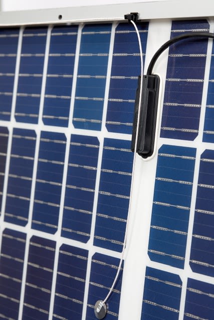
We also upgraded the sensor cable using a thin Teflon cable. The thinner cross-section of the cable minimizes shading of the rear face of the PV cells on the panel and increases the sensor’s maximum temperature rating. It is also easier to route the cable through the space between the cells.
The sensor head is redesigned to be more efficient in measuring the true temperature of the back sheet. Surface cooling is a common problem observed with other types of BOM temperature sensors. To overcome this issue, we used careful thermal modeling to optimize the probe design, promoting heat transfer between the back sheet and the probe head and, at the same time, preventing localized cooling of the surface being measured. The sensor head covers about 2% of the rear side area of a full-size cell. This results in negligible shading of the individual cell.
All these sensor updates were made while maintaining the same accuracy of its predecessor—the Class A resistance temperature detector (RTD). The temperature uncertainty is ±0.3° to 0.4°C in the measurement range of -40° to +100°C when measured using the CR1000X Measurement and Control Datalogger. The new sensor has been released as the CS241. To meet the increasing requirements of performance validation, every CS241 sensor ships with a NIST-traceable serialized calibration certificate.
Our BOM sensors are designed to help you get the most reliable and accurate data. To find the sensor that would best benefit your project, visit our Solar Energy solution page or learn more about the CS241 on the CS241 product page.
Image Descriptions
The first image in the article shows a CS241 sensor installed in the field with the sensor wire neatly routed between the cells. This method can be used on PV panels using half-cut or full cells.
The second image in the article features a CS241 sensor installed on a bifacial panel with half-cut cells. The sensor ships with the special zip ties to route the sensor cables neatly and attach them to the frame of the module.
Credit
Matt Perry, Technical Product Manager of the Renewable Energy Group at Campbell Scientific, Inc., contributed to this article.
Reference
1Deline, C., Peláez, S. A., Marion, B., et al., "Bifacial PV System Performance: Separating Fact from Fiction," (presentation at 46th IEEE Photovoltaic Specialists Conference [PVSC 46], Chicago, Illinois, June 19, 2019). https://www.nrel.gov/docs/fy19osti/74090.pdf


 Dr. Ajay Singh is a Product Manager in the Renewable Energy Group at Campbell Scientific, Inc. His work is focused on PV soiling measurement and mitigation, solar resource assessment, and solar radiation measurement. He has a doctoral degree in physics.
Comentarios
Please log in or register to comment.