PC-TDR Software soporte para TDR100


Resumen
Current Version: 3.0
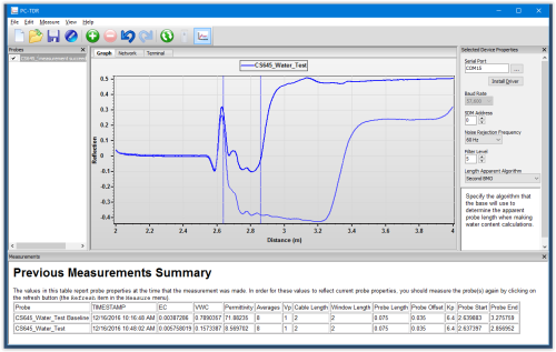
PC-TDR software is used with our TDR200 and retired TDR100-based systems during system configuration, testing, probe calibration, and troubleshooting. It displays and collects TDR waveforms, displays volumetric water content and electrical conductivity measurements, and generates CRBasic programs to facilitate TDR data collection on current Campbell Scientific dataloggers.
Ventajas y características
- Designed to work with the new TDR200 while remaining fully compatible with the retired TDR100 Time-Domain Reflectometer
- Compatible with current Windows operating systems (support for Windows 10/11)
- Advanced CRBasic program generator for both TDR200 and TDR100 systems, including support for the SDM8X50 and SDMX50 multiplexers, as well as default probe settings for all Campbell Scientific-built TDR probes
- Probe Calibration wizard to determine probe specific lengths, offsets, and Kp values for all Campbell Scientific or third-party probes
- Graphical TDR network setup based on Network Planner, allowing for easy setup and programing
- View the TDR Trace, 1st derivative, or 2nd derivative waveforms of multiple probes within the same graph
- Quickly toggle baseline measurement from the graph view
- Graphically display the beginning and ending reflection for water content measurements
- Import/Export TDR probe data using TOA5 or XML file formats
- Allows access to the new TDR200 features including 60/50 Hz noise reduction, advanced TDR filtering, and the ability to measure up to 10,112 discreet points along a window length
Imágenes

Productos similares
Preguntas frecuentes
Número de FAQs relacionadas con PC-TDR: 10
Expandir todoDesplegar todo
-
Yes. In PC-TDR, click Settings/Multiplexer and Add Mux.
-
No. A Windows-based computer is required to run PC-TDR.
-
To understand the readings obtained from a datalogger program, it is necessary to see how the TDR100 operates in PC-TDR. Either the TDR100 commands are entered in PC-TDR and the user waits to see the results, or the datalogger sends the TDR100 commands and automatically stores the results.
Campbell Scientific suggests initially entering the TDR100 commands in PC-TDR and waiting for the results before writing a datalogger program. This allows verification that the TDR100 is operating correctly in PC-TDR. After that has been verified, a datalogger program can be created for the TDR100 that sends the commands and stores the results.
-
Although slope stability/rock mass deformation users will need to adjust the following PC-TDR default settings, these settings may provide a good starting point:
- Cable VP = 1.
- Waveform Average = 4.
- Waveform Points = 251.
- Waveform Start = 0.
- Waveform Length = 50.00.
Note that the Probe Length and Probe Offset will not be used for a slope stability/rock mass deformation application.
-
Yes. PC-TDR can send control commands to advance through the channels of a SDMX50-series multiplexer. To do this, select Settings | Multiplexer and then add the multiplexers and probes that match the TDR100 system.
-
No, as of September 2014. The PC-TDR support software can be downloaded free-of-charge from the Downloads section of the PC-TDR product page.
-
There are several possible things that should be considered or verified:
- Verify that there is 12 V dc on the TDR100 green connector. A reading between approximately 10 V to 16 V dc is OK.
- Use a standard RS-232 serial cable to connect from the PC 9-pin RS-232 communications port to the TDR100.
- Verify that PC-TDR is set up for the correct PC communication port. To do this, enter the PC_Com_Port in PC-TDR/Settings/Communication/Com_Port=??User specific??.
- Note: Keep the baud rate set at 57.6.
- Verify that the TDR.ini file is set for the correct COM port. To do this when PC-TDR is closed, use a tool such as Windows Notepad to view/edit the TDR.ini file on a PC.
- Example:
- The PC’s USB to RS-232 adapter is displayed as COM7 in PC-TDR.
- Close PC-TDR.
- In the C:\Campbellsci\PCTR\TDR.ini file, change the CommPtEx=1 line to CommPtEx=7.
- Note: When a PC does not have a 9-pin RS-232 communications port, consider using pn 17394, USB-to-9-Pin Male RS-232 Cable.
- Example:
- If there are still communication issues, make sure that other software packages (such as PC200W, PC400, and LoggerNet) that use the PC_Com_Port are closed when running PC-TDR. Otherwise, these software packages will be in conflict over access to the PC_Com_Port.
- Close PC-TDR.
- Cycle power on/off to the TDR100.
- Open PC-TDR.
- Verify Com_Port=??User specific??.
- Note: Keep the baud rate set at 57.6.
- Either click PC-TDR Get Waveform or Water Content.
-
The PC-TDR software is compatible with the SDM8X50 multiplexer, but the non-latching relays may cause issues. When PC-TDR (version 2.08 and lower) advances to a multiplexer terminal, it sends one command to the multiplexer. With the older SDMX50-series multiplexers, one command was sufficient because the relays latched. The non-latching relays on the SDM8X50 release 30 seconds after the command is sent, which results in a loss of connection between the sensor on that terminal and the TDR100. To latch again for a good reading, it is necessary to manually force PC-TDR to go to a different SDM8X50 terminal and then back to the terminal of interest. The continuous waveform function should not be used with the SDM8X50. These known issues will be addressed in the next version of the PC-TDR software.
-
The TDR100 should work with most good quality USB-to-serial converters, such as the 17394 USB-to-9-pin Male RS-232 cable. To use such an interface, determine which virtual serial terminal it represents, and use that serial terminal in PC-TDR. Early versions of PC-TDR were limited to COM1─COM4. Later versions work with a wider range of COM terminal numbers.
-
This error occurs if the COM port that was last used by PC-TDR cannot be opened because it is already opened or no longer available. The error is most often seen when either of these two scenarios occurs:
- A previously used USB-to-serial cable is no longer connected.
- The COM port number assigned to the device has changed.
To resolve the error, open the TDR100.ini file found in C:\Campbellsci\pctdr and change the CommPtEx setting to a valid COM port number (for example, CommPtEx=1). Alternately, the TDR100.ini file can be deleted, although this will reset any previously entered wave-form values, as well as any user-defined coefficients.
Compatibilidad
- PC-TDR software is used with our TDR200 and retired TDR100-based systems.
- PC-TDR is compatible with current Windows operating systems (support for Windows 10/11).
- An available USB port is required to connect to the TDR200, and a USB-to-serial adapter may be required to connect to the retired TDR100.
Especificaciones
| Current Version | 3.0 |
Descargas
PC-TDR v.3.0 (7.34 MB) 15-12-2016
Support software designed for the TDR200 and is also compatible with the retired TDR100 Time-Domain Reflectometer.
