Gama de productos

Preguntas frecuentes
Número de FAQs relacionadas con Sensores: 8
Expandir todoDesplegar todo
-
Whenever possible, purchase a sensor with the desired cable length. Some sensors have a user-specified cable length, whereas other sensors have a set cable length.
Sometimes, an old cable can be replaced with a new, longer cable.
Generally, additional cable cannot be spliced onto the existing cable because:
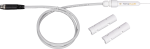
- Some sensor cables have bridge completion resistors at the pigtail end
- Some sensors are calibrated based on cable length
- Sometimes the color in the insulation is not the same as that visible at the pigtail end
- It is possible to introduce errors or malfunctions depending on the integrity of the splice
Splicing cable together increases the likelihood that water may enter the cable and cause shorting, corrosion, and some other potential issues, which in turn can cause measurement issues.
Because of the potential issues, do not splice any sensor cable without first contacting Campbell Scientific to discuss the sensor in detail.
-
Sometimes, an old cable can be replaced with a new, shorter cable.
Sometimes, an existing cable can be shortened by cutting the ends off. However, there are a few issues that could be encountered when doing this:
- Some sensors have bridge completion resistors at the pigtail end.
- Some sensors are calibrated to length.
- Sometimes the color in the insulation may not be the same as that visible at the pigtail end.
Because of the potential issues, do not cut the ends off any sensor cable without first contacting Campbell Scientific to discuss the sensor in detail.
-
No. Depende del fabricante del sensor y del pedido. Si viene por defecto se indica en la columna de la derecha de la página web del producto, o en el folleto o manual del sensor.
-
Most Campbell Scientific sensors are available as an –L, which indicates a user-specified cable length. If a sensor is listed as an –LX model (where “X” is some other character), that sensor’s cable has a user-specified length, but it terminates with a specific connector for a unique system:
- An –LC model has a user-specified cable length for connection to an ET107, CS110, or retired Metdata1.
- An –LQ model has a user-specified cable length for connection to a RAWS-P weather station.
If a sensor does not have an –L or other –LX designation after the main model number, the sensor has a set cable length. The cable length is listed at the end of the Description field in the product’s Ordering information. For example, the 034B-ET model has a description of “Met One Wind Set for ET Station, 67 inch Cable.” Products with a set cable length terminate, as a default, with pigtails.
If a cable terminates with a special connector for a unique system, the end of the model number designates which system. For example, the 034B-ET model designates the sensor as a 034B for an ET107 system.
- –ET models terminate with the connector for an ET107 weather station.
- –ETM models terminate with the connector for an ET107 weather station, but they also include a special system mounting, which is often convenient when purchasing a replacement part.
- –QD models terminate with the connector for a RAWS-F Quick Deployment Station.
- –PW models terminate with the connector for a PWENC or pre-wired system.
-
Not every sensor has different cable termination options. The options available for a particular sensor can be checked by looking in two places in the Ordering information area of the sensor product page:
- Model number
- Cable Termination Options list
If a sensor is offered in an –ET, –ETM, –LC, –LQ, or –QD version, that option’s availability is reflected in the sensor model number. For example, the 034B is offered as the 034B-ET, 034B-ETM, 034B-LC, 034B-LQ, and 034B-QD.
All of the other cable termination options, if available, are listed on the Ordering information area of the sensor product page under “Cable Termination Options.” For example, the 034B-L Wind Set is offered with the –CWS, –PT, and –PW options, as shown in the Ordering information area of the 034B-L product page.
Note: As newer products are added to our inventory, typically, we will list multiple cable termination options under a single sensor model rather than creating multiple model numbers. For example, the HC2S3-L has a –C cable termination option for connecting it to a CS110 instead of offering an HC2S3-LC model.
-
Many times, but not always, a sensor’s cable can be replaced with a new cable. This is helpful if the original cable was damaged or if its length needs to be changed.
If the cable is attached to the sensor using a connector, Campbell Scientific will sell a replacement cable. For example, a 05106CBL-L is a replacement cable for a 05106-L. Replacement cables are listed in the “Replacement Parts” section of the Ordering information area of the product page.
If the cable is attached to a sensor through a user-accessible terminal block, a raw cable can be purchased to replace it. For example, to replace the cable on a 05103-L Wind Monitor, order the desired length of pn 9721, 24 AWG 3 Twisted Pair Shielded Santoprene Cable. As another example, the raw cable for a TE525-L Rain Gage is pn 9661, 22 AWG 1 Twisted Pair Shielded Santoprene Cable.
If the cable is an integral part of the sensor, the cable cannot be user replaced, and the sensor must be returned to Campbell Scientific. Some examples of sensors that fall into this category include the 107-L, 109SS-L, 229-L, CS547A-L, and CS650-L. For the process of returning equipment to Campbell Scientific, refer to the Repair and Calibration page.
-
Many Campbell Scientific sensors are available with different cable termination options. These options include the following:
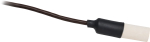
- The –PT (–PT w/Tinned Wires) option is the default option and does not display on the product line as the other options do. The cable terminates in pigtails that connect directly to a datalogger.
- In the –C (–C w/ET/CS110 Connector) option, the cable terminates in a connector that attaches to a CS110 Electric Field Meter or an ET-series weather station.
- In the –CWS (–CWS w/CWS900 Connector) option, the cable terminates in a connector that attaches to a CWS900-series interface. Connection to a CWS900-series interface allows the sensor to be used in a wireless sensor network.
- In the –PW (–PW w/Pre-Wire Connector) option, the cable terminates in a connector that attaches to a prewired enclosure.
- In the –RQ (–RQ w/RAWS Connector) option, the cable terminates in a connector that attaches to a RAWS-P Permanent Remote Automated Weather Station.
Note: The availability of cable termination options varies by sensor. For example, sensors may have none, two, or several options to choose from. If a desired option is not listed for a specific sensor, contact Campbell Scientific for assistance.
-
Voltage Measurements
The effect of long cable lengths on analog measurements depends on the type of measurement that is made. For example, long lead lengths do not affect differential measurements of passive sensors (e.g., thermocouples, thermopiles, photo diodes), or active sensors that have a separate lead for the signal reference and the power ground, such as the CS106 Barometric Pressure Sensor. Making a differential measurement on an active sensor that shares the same lead for the signal reference and power ground (e.g., HMP60 Temperature and Relative Humidity Probe) does not eliminate the effects of long lead lengths.
So, what is the problem with long lead lengths? The problem is that when current flows through a ground wire, there is a voltage drop. The voltage drop follows Ohm’s law and causes an apparent voltage increase between the signal lead and the signal reference lead. This voltage drop occurs because wires have resistance. Long lengths of wire have more resistance than short lengths. Thus, long lengths of wire will cause a larger voltage drop than shorter lengths. Also, the voltage drop is more pronounced in active sensors (sensors that require 12 Vdc to operate) than in passive sensors, because there is more current flowing in the ground wires of the active sensors.
The HMP45C Temperature and Relative Humidity Probe draws approximately 4 mA at 12 Vdc when it is powered. The cable (p/n 9721) used in the HMP45C has a resistance of 27.7 W/1000 ft. For a Single-Ended Measurement (Instruction 1), the signal reference and the power ground are both connected to ground at the datalogger; the effective resistance of those wires together is half of 27.7 W/1000 ft, or 13.9 W/1000 ft. Using Ohm’s law, the voltage drop, Vd, along the signal reference/power ground, is given by the equation below:
Vd = I * R
Vd = 4 mA * 13.9 ohm/1000 ft
= 55.6 mV/1000 ftThis voltage drop will raise the apparent temperature and relative humidity because the difference between the signal and signal reference lead, at the datalogger, has increased by Vd. The approximate error in temperature and relative humidity is 0.56°C and 0.56% per 100 ft of cable length, respectively.
Since the HMP45C is fitted with both a wire for the signal reference and power ground, its output can be measured using a Differential Measurement (Instruction 2). The voltage drop, as described above, will not occur on the signal reference lead, because the datalogger’s High and Low Analog Input Channels, used to make a differential measurement, are high impedance, i.e., no current can flow into them.
In general, use a Differential Measurement to measure sensors with long lead lengths. For sensors that require 12 Vdc to operate, use two separate leads for the signal reference and the power ground.
Bridge Measurement
The signal from bridge measurements suffers the same voltage drops when long lead lengths are used to connect the bridge to the datalogger. (See the above section.) Again, a differential measurement, as used in the 4 Wire Half Bridge (Instruction 9) or 6 Wire Full Bridge (Instruction 9), can be used to eliminate this voltage drop. There are two additional complications in bridge measurements--the excitation voltage and the setting time.
Bridge measurements require that the datalogger excite the bridge with a precision excitation voltage. When long lead lengths are used to connect the bridge to the datalogger, the excitation voltage, at the bridge, will be less than the excitation voltage at the datalogger. This voltage drop is caused by the resistance of the wires connecting the bridge to the datalogger’s excitation channel. The excitation voltage drop can be compensated for by using a 3 Wire Half Bridge (Instruction 7), 4 Wire Half Bridge (Instruction 9), or 6 Wire Full Bridge (Instruction 9) measurement.
It takes a finite amount of time for the excitation voltage and signal voltage to stabilize to its true value. This time will vary with the lead length. For more information, see the "Effect of Sensor Lead Lengths on the Signal Settling Time" section in the datalogger manuals (Section 13).
In general, if long lead lengths are required for bridge measurements, use the 3 or 4 Wire Half Bridge configuration over the 2 Wire and the 6 Wire Full Bridge configuration instead of the 4 Wire Full Bridge. See the "Bridge Resistance Measurements" section in the datalogger manuals (Section 13).